
How to improve radiant heat performance in radiant tube (radiant tube) using additive production technology in continuous annealing line
Review:
This study investigates the application of additive manipulation (AM)technology in a W-type radiant tube to improve radiant heat performance. The appropriate dimensions of the honeycomb structure are determined by finite element analysis (FE) and the radiative heat gain is calculated. Honeycomb patterns are punched on RT (radiant tube) surfaces using the direct energy depsitin (DED) method. The radiant thermal efficiency of the RT prototype was investigated using a honeycomb pattern installed in a test furnace by imitating a continuous annealing line (CAL). Finally, the quality of the RT prototype was tested on site at CAL No. 3CGL at POSCO Gwangyang Steel Works. The results show that partial analysis of FE, which predicts the amount of radiant heat by modeling part of the RT structure instead of modeling the entire RT structure, is suitable for overcoming the limit of computer memory capacity and calculating honeycomb pattern design parameters. DED Suitable for printing honeycomb patterns on RT with large, curved surfaces. The average gas consumption to maintain 780 ° C and 880 ° C for 1440 minutes is reduced by 10.42% and 12.31%, respectively. During the three-year annual inspection, there were no cracks or gas leaks at the RT level.
1. Introduction
Additive manufacturing (AM) has emerged as an advanced technology due to its various advantages, including the ease of manufacturing complex geometric components and improving the performance of expensive raw materials. AM delivery time is usually short. AM components (made from the AM process) can be used in a variety of contexts and contribute to the system to which they belong in a variety of ways. For example, overall system performance is enhanced by high-performance AM components, while lighter AM components can reduce power consumption.
The end product of the continuous annealing process is a cold-rolled steel strip. In this process, the strips are stored in a reheating furnace, stabilized with barley and without chemical changes. This type of annealing is done in a continuous annealing line (CAL), commonly called CAL in the steel industry.
POSCO is looking for processes that can reduce fuel consumption using AM due to strict environmental regulations. CAL consumes a large amount of fuel to maintain a predetermined heat treatment temperature (approximately 800-1000 ° C). بسته به مقدار CAL، تقریباً 100-500 لوله تابشی در CAL در حال کار است و هر ساله حدود 300 میلیون مترمکعب گاز کک (coke oven gas(COG)) و گاز طبیعی مایع (liquefied natural gas(LNG)) مصرف میشود. The radiant heat is continuously released from the outer surface of the radiant tubes, while the combustion heat is charged and then continuously released through the radiant tubes of the inner surface.
A radiant tube (RT) consists of a burner, a recycler, and a tube made of high-temperature steel or nickel-based alloys. In the burner, fuel (LNG Or COG) ignites and enters the RT input quickly. The heat generated at high temperatures in the pipe is transferred by radiation from the outer surface of the pipe to the steel strip. Finally, the heat escapes through the outlet. The hot exhaust gas recovered by the regenerator is then used to heat the cold air flowing from the burner. RT comes in a variety of forms: Double P, straight, WU.
Much research has focused on improving the radiant heat performance of the burner and the RT reheating system. Flamme Et al. (2010) argued that increasing fuel efficiency depends on warming the cold air flowing through the burner. Therefore, they stressed the importance of RT design that can use internal preheating technology such as recovery plugs and regenerative and recovery burners. Therefore, they stressed the importance of RT design that can use internal preheating technology such as recovery plugs and regenerative and recovery burners. They reported that the use of low-temperature gas stations that can burn at low temperatures reduces fuel costs and thus increases fuel efficiency. In 2006, Scribano et al. Tried to find the best RT operating conditions in terms of equivalence ratio, thermal power, and lower emissions. They designed the mechanism of automatic rotation of the exhaust gases and the NOx emission rate for a wide range of thermal power ratios and equivalence up to 50%, compared to the original design of the burner without compromising the thermal efficiency, CO emissions And reduced the surface temperature uniformity of the RT.
In this paper, a method to improve the RT radiant heat efficiency of type W in CAL using AM is presented. The RT level increases by printing a series of honeycomb patterns on the RT surface. To calculate the integrated irradiation time per unit area (thereafter, as radiant heat (J / s)) and to determine the appropriate dimensions (width, length and thickness) of the honeycomb printed on the RT surface by three-dimensional finite thermal elastic element analysis (FE) Done.
The RT is large (the size of a straight tube is 19x 2000 Mm) and has a curved surface. As a result, it is impossible to print a set of honeycomb patterns using the bed powder mixing (PBF) method. Therefore, in this research, the directed energy deposition (DED) method has been selected This method can be used even on large and curved objects. DED printers and powders Available on the market (INCONEL 718 alloy) is used.
Radiant heat efficiency RT Were evaluated with honeycomb patterns printed in an experimental furnace. RT It is supported by refractory support at the far end of the test furnace, while maintaining two ambient temperatures (780 ° C and 880 ° C) in CAL. For comparison, RTs with and without honeycomb patterns are installed sequentially in the experimental furnace. Instead of measuring radiant heat, changes in the amount of gaseous fuel consumed to maintain a specific ambient temperature are measured in a test furnace. Finally, the correctness of the RT prototype was tested with honeycomb patterns printed on site with real CAL No. 3CGL at POSCO Gwangyang Steel Works, Korea.
2. FE tape analysis and RT
2.1 Honeycomb pattern design variables
Figure 1 shows a picture of a real W-type RT structure consisting of four straight tubes, three U-bends, a torch and an improver. The pipes are made of INCONEL 601 cold rolled tapes with a thickness of 3 mm. The burner is installed at the inlet of the first straight pipe and the improver directs part of the heat output of the burner at the outlet of the fourth straight pipe. Figure 1b and c shows a set of Pratt truss patterns and honeycomb patterns generated at the RT level for FE analysis. The radiant thermal efficiency of Pratt truss and honeycomb shape has been calculated and their radiant heat efficiency has been compared. The structure (shape) of the honeycomb has been chosen because its radiant heat efficiency was better and its diffusion rate theoretically reaches 0.98. Figure 1d shows a schematic of the honeycomb pattern and its design variables. The variable “t” indicates the height of the honeycomb network in the direction of the tube radius.
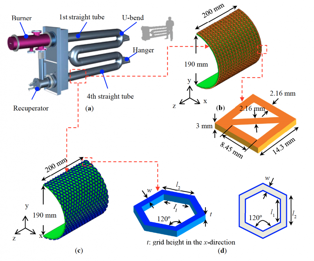
figure 1. (A) The shape and size of a true radiant tube (RT). B) A set of Pratt truss patterns that is created in a part of the straight pipe surface. (C) A set of honeycomb patterns that form on a portion of the straight tube surface. (D) Schematic of a honeycomb and design variables ‘W‘ which indicates the width of the honeycomb network. L1 and l2stands for inner and outer length of honeycomb.
2.2 RT heat transfer model
The pre-concept CAD design, which includes a set of honeycomb patterns printed on the RT, serves as the basis for its heat transfer model from the RT. The following modes are intended for heat transfer.
Radiation exchange between the RT surface and the sloping strip.
Guide through the thickness of the tube and a set of honeycombs printed on it.
Convection heat transfer is neglected due to the movement of a very small amount of liquid through the RT during operation. To shorten the computation time and overcome the limit of computer memory capacity, a straight tube with a length of 200 mm was modeled and analyzed. The semi-directional longitudinal FE model (Y-Z plane) is shown in Figure 1c. Henceforth, for convenience, this type of FE model is called the “partial FE model”.
Radiant heat exchange between the surface of the partial FE model and the surface of the steel strip is assumed to be a radiation problem cavity with a gray body, and scattered reflections between the surfaces. A hole in Abaqus / Standard is defined as a set of surfaces consisting of faces. Cavity irradiation problems are inherently nonlinear due to T4 dependence on charge. Further nonlinearity can be described as a function of temperature by describing radiation (E). The radiant heat flux at the surface of the cavities is defined by Equation (1).

Where N is the number of plates forming the cavity, Fij is the geometrical factor matrix, s Stephen-Boltzmann, and ej are the Ti and Tjradiations of the facesi and j, respectively. Cij is the reflection matrix defined by Equation (2).

dijrepresents the performance of the Delta Cronker.
Radiation heat transfer between opposite surfaces strongly depends on the geometry and orientation as well as their radiant properties and temperature. The amount of radiant heat transfer on both sides is defined by the Fij factor. Figure 2 is a schematic of the visibility factor defined as the fraction of surface crack radiation (dAs) by the surface (dAj). Equation (3) defines the visibility factor between two surfaces with distance R.

Rij Distance between planes dAi, dAj, qIand qj, polar angles between Rij And are normal surface. For the closed cavity problem, the visibility factor satisfies the correlation (A Fij = AjFji). The sum of the visual factors calculated in each hole is 1 (Equation 4)


C3D8T element (8-node node coupling brick, three-line displacement and temperature) was used for FE analysis with temperature displacement. A mesh convergence test was performed to determine the appropriate element size. The aspect ratio of the elements used for the geometric modeling relative to the partial FE model was 1.5 (width, weight): 0.1 (length, 11): 1.5 (height, t), and 100,788 elements were used.
2.3 Initial condition, boundary condition and observation factor curve
Figure 3 shows the isometric view of the partial FE model. The elements in the honeycomb pattern are highlighted in blue and the elements in the steel strip are highlighted in gray. The initial temperature of the partial FE model and the steel strip was set at 20 ° C.

Figure 3. (A) Isometric view of partial FE model (b) Steel travel (c) Front view of partial model FE
In a true CAL process, the temperature profile throughout the RT is not uniform and the temperature decreases as the distance from the burner increases, as shown in Figure 4. This temperature profile was measured by Ifran et al. In 2010 and approved in this study. The average temperature (905 ° C) of the four points A, B, C, and D (points marked in black in Figure 4) is a straight tube as the boundary condition for the partial FE model and hence the temperature (905 ° C) to the inner surface. The partial FE model was applied.
The visibility factor varies with the distance between the surface of the pipe and the surface of the steel strip. The visibility factor curve in the FE analysis is shown in Figure 5. The distance between the strip and the center of the tube is 305 mm. In the cavity irradiation, the small face surface ratio was at least 84, the Gaussian integration points at each edge were 3, and the square distance-area value was 5. The amount of irradiation of the main surface and the surface of the slave was determined to be 0.77. The ambient temperature was adjusted between the partial FE model with the honeycomb pattern and the 800 ° C strip.

Figure 4. Temperature profile measured in the direction of actual length RT

Figure 5. Observation curve used in FE analysis.
2.4 Materials
Mechanical and thermal properties of RT material (INCONEL 601 At 900 ° C) is listed in Table 1. Constant Stefan Boltzmann 5.669 x 10⁻¹⁴ W / mm2 / K4 And is set to absolute zero at 273.15 ° C below zero.

Table 1. Mechanical and thermal properties of INCONEL 601 at a temperature of 900 ° C.
2.5 Determining bee spot design variables
Radiant heat calculation(J / s) FE analysis was performed when the printed RT surface with the honeycomb pattern facing the steel strip. The ratio of 200 mm (width of the tube in the direction of length) to 300 mm (width of the steel strip) was placed in the partial FE model, which coincides with the ratio of the average straight RT length of the actual RT on which the honeycomb pattern is located. Printed across the width of a real steel strip that is annealed in real CAL. The distance between the RT and the steel strip is 305 mm, which is usually applied in real practice. The thickness of the steel strip is 3 mm. The analysis was performed using a partial FE model to reduce the computation time.

Figure 6. (A) Honeycomb design variables (left). model Partial FE with printed honeycomb patterns (right). (b-d) Dimensions of honeycomb structures used in the analysis Indicates FE. ‘t indicates the height of the honeycomb network in the direction of the tube radius. (e-g) Line indicator RADTLA, integrated heat radiation time per unit area (J / s) for the three honeycomb structures above.
The three different honeycomb structures shown in Figure 6b-d are considered in the FE analysis to determine the design variables of a honeycomb structure. Figure 6b is the honeycomb structure of the smallest printable sizes in this study. Figure 6c, d shows the honeycomb structures. Other sizes of honeycomb structures are also considered. Figure 6 e-g Computed radiant heat compares three honeycomb patterns with different dimensions (width, length and thickness). The radiant heat change along the central longitudinal nodes of the strip is significant. Hence, radiant heat is calculated as the average radiant heat along the middle longitudinal nodes (Y direction) of the strip. The radiant heat of the 6e-g valley is 548.6 (J / s), 564.5 (J / s) and 527.8 (J / s), respectively. Note when the level The RT without the honeycomb pattern faces the bar and the honeycomb design variables shown in Figure 6 f, radiant heat compared to radiant heat RT without honeycomb pattern increases by approximately 8.64% Radiant heat 519.6 (J / s) is. Therefore, in this study, honeycomb design variables in Figure 6f have been selected for DED printing.
RT deviation due to honeycomb pattern weight has also been investigated. The difference in maximum RT deviation due to the addition of the honeycomb pattern is only 0.0021 mm (0.14%). بنابراین، نتیجه میگیریم که افزایش وزن ناشی از افزودن الگوی لانه زنبوری بر روی RT اثر ناچیزی در انحراف RT دارد.
3. Testing
3.1 Materials used to print honeycomb pattern
INCONEL 718 alloy powder (CarTech®718, UNS N07718), with the chemical composition listed in Table 2 (prepared by Carpenter Technology Corporation), uses INCONEL 601 to print a set of honeycomb patterns made in RT. Ideally, the pattern metal should be the same as the RT metal to achieve high bond strength between the pattern and the RT surface and to prevent the patterns from separating from the RT during repeated heating and cooling of the printed RTs from the pattern. However, the selected pattern material INCONEL 718 is an option because INCONEL 601powder is not commercially available for 3D printing.

Table 2. Chemical composition (mass percentage) of INCONEL 718 alloy powder prepared by Carpenter Technology Corporation. Fe
Table 3 shows that INCONEL 718 has higher tensile strength and performance than INCONEL 625 at high temperatures. The higher resistance pattern can support RT and prevent it from falling at high temperatures. Table 4 shows that the difference between the thermal expansion coefficients ofINCONEL 601 and INCONEL 718 is smaller than that of INCONEL 601 and INCONEL 625. Therefore,INCONEL 718 is more effective in preventing patterns from separating from RT when RT templates are repeatedly heated and cooled during printing.

Table 3. High temperature resistance of INCONEL alloy candidates

Table 4. Thermal expansion coefficient of INCONEL alloy candidates
The particle size distribution of INCONEL 718 powder is performed using the Malvern Mastersizer 3000 and the morphology of the particles is observed through scanning electron microscopy (SEM). Figure 7a shows the particle size distributions for D10, D50 and D90 at 57.1um, 95.5um and 155um, respectively. Unlike the PBF method, powders with a wide range of particle sizes can be used in the DED process, which has the advantage of reducing the cost of making DED. The particle size of the powder for the DED method is similar to that used in powder metallurgy processes, 50-150 mm, and the powder used is comparable in size.

Figure 7. (A) Particle size distribution based on the volume of INCONEL 718 powders (b) SEM image of INCONEL 718 powder with low magnification (c) SEM image of INCONEL 718 powder with high magnification.
Figure 7b shows the SEM images ofINCONEL 718 powders. The overall shape is almost spherical (Figure 7c), and the individual powder particles have a dendritic microstructure, typically the result of rapid freezing while some satellites cling to larger particles (Figure 7c).
3.2 DED printing machine
Direct energy deposition (DED) One of the processes is AM where a concentrated energy source (laser beam, electron beam and plasma arc) is used to form a deposition layer with metal powder or wire. DED compared to powder bed fusion (PBF) offers faster fabrication speeds and larger print sizes, and can attach additional materials directly to existing parts..
TheInssTek MX-Grande (Korea) is used to print honeycomb patterns. The process parameters required to operate the machine are given in Table 5. The laser power is automatically set between 500 and 800 watts. The height of the molten pool was analyzed and controlled in real time using two cameras mounted on the nozzle head. Printing is limited to the surface of four straight RT tubes except 20 mm at the end of each straight tube to create the space required for welding straight tubes and U bends.

Table 5. DED process parameters used forINCONEL 718 printing
3.2 Print honeycomb patterns on the (real) RT prototype
The DED printer on the market is used because it can print them on a straight tube with large and curved surfaces. In the DED process, the powder is placed in successive layers on the surfaces and melted by different heat sources of the powder to be produced in any shape. In this study, a layer is defined as a separate flat and a honeycomb shape.
There are two ways to print a set of honeycomb patterns on surfaces. The first method divides the target height of the honeycomb shapes on a straight tube into a certain number of layers, and then each layer is placed on top of the printed layers, respectively. In this study, the thickness of one layer of the honeycomb shape was 500 cm, and therefore, six layers were stacked on top of each other to form a 3 mm high honeycomb. Each layer is repeatedly glued to the previous layer until it reaches the target height (3 mm) of the honeycomb. From now on, this method is known as the “layer priority method”.
Another method divides a straight pipe in a peripheral direction into a certain number of loops. The outer ring area is referred to as the section. In this study, straight tubes were divided into 16 sections. Honeycomb patterns with a height of 3 mm were printed at once in the first part and then the honeycomb pattern was printed in the next part, respectively. With this method, honeycomb patterns were printed in 16 sections. From now on, this method is known as the “prioritization method”.
The honeycomb pattern shown in Figure 8a, b is constructed using the prioritization method. Figure 8a, for example, shows the first layer of the honeycomb pattern at the edge of a straight pipe 2000 mm long with a diameter of 190 mm with a rotating stick. The printer head and chuck move simultaneously to print the honeycomb pattern. Figure 8b An overview shows the prototype RT with a printed honeycomb pattern to be installed in the test furnace.
3.4 Measurement of temperature and fuel consumption of RT prototype
The radiant thermal efficiency of the RT prototype was tested with a printed honeycomb pattern using an experimental furnace. Figure 9a shows a schematic of a test furnace that mimics the actual CAL. This test furnace produces a state in which the radiant heat generated by the RT prototype is absorbed by the steel strip. Two full-size RT (prototype) without honeycomb patterns are supported by refractory support in the second chamber and chamber, ie the test furnace has a heat-resistant glass viewing window and an adjustable valve at the air inlet and outlet. To be. The chamber is made of thermal insulation bricks and its walls are covered with heat-resistant wool. Figure 9b shows each part of the test furnace. The ambient temperature inside the test chamber was measured in four positions (# 1, 2, 3, 4) 200 mm from the straight tube where the steel strip is located in the actual CAL. The temperature value at position 2 was used to control fuel consumption during the test. The temperature and gas control system controls the ambient temperature by adjusting the amount of fuel consumed by the burner.

Figure 8. (A) The first printed layer of the honeycomb pattern at the edge of a straight tube 2000 mm long. (ب) الگوهای لانه زنبوری بر روی سطح لوله مستقیم نمونه اولیه RT چاپ شده تا در کوره آزمایشی نصب شود.

Figure 9. (A) Schematic of an experimental furnace that evaluates the radiant heat efficiency of full-size RTs with and without honeycomb patterns. (B) Description of each component in the test furnace.
Two RT prototypes work with and without honeycomb patterns in the heat cycle, as shown in Figure 10. The heat treatment temperature is usually used in real CAL and the soaking time at both 780 and 880 ° C was 1440 minutes (24 hours). Changes in fuel consumption were measured while maintaining the ambient furnace ambient temperature for 24 h.

Figure 10. Temperature changes and heat storage operation and storage time (heat cycle) commonly adopted in a test furnace.
4. Results and discussion
4.1 3D printing pattern
As mentioned above, when printing a set of honeycomb structures using a DED printer, two methods are used to prevent thermal deformation of the thin tube (3 mm thick) during printing.
Figure 11a shows the pattern printed with the layer priority method. Layer priority method prints each layer section by section. To prevent heat concentration, each part is printed away from the previously printed part. This method is effective for heat dissipation. However, this causes the position of the next printed layer to deviate from the previous printed layer because the entire printing area heats up and the tube expands thermally. Figure 11b is a larger image of the printed pattern using the layer priority method. Some splashes are seen on the edge. A terraced layered structure was obtained instead of a transparent honeycomb structure. This is due to the accumulation of the printed layer at different times. The amount of thermal expansion of each layer increases with the number of pattern layers.
Figure 11c prints the honeycomb pattern using the section prioritization method. Figure 11d is a larger image of the pattern printed with the prioritization method. Although there is a slight discrepancy between the first and second layers, the whole honeycomb pattern is well printed. In this method, the heat is concentrated in a relatively small area. Therefore, only the heated part expands. However, in the layer priority method, a total of 16 sections are heated to print the first layer in all sections. These 16 sections expand. Although the heat input of a section in the cross-section prioritization method is higher than the layer priority method, the heated area is smaller and the layer after the third layer is printed on a fully heated and expanded section. As a result, the layer mismatch in the prioritization method is smaller than the layer priority method.

Figure 11. Honeycomb patterns printed by layer preference method. (A) full view and (with) large view. Honeycomb patterns printed with priority method. C) Full view and (in) large view.
4.2 Spraying on the pattern
Weld spraying at the edge is shown in Figure 11b, d. Welding spray is a drop of molten metal that is dispersed from the molten pool during printing. In the initial stage of printing, the spray is attached to the fabrication plate because the position of the molten pool is close to the fabrication plate and the dispersed melt droplets are still in one liter. Liquid state (outside the oxide film and inside the liquid metal) or semi-liquid state when adhering to the fabrication plate. As printing progresses, the position of the molten pool increases due to the accumulation of the printed layer. Scattered molten droplets solidify as the melt droplets increase in flight distance before adhering to the fabrication plate. Therefore, spraying for printing a large independent part does not pose a serious problem because the fabrication plate attached to the sprayer is removed after printing.
In the case of printing additional structures or repairing damaged areas on existing parts, however, the position of the molten pool is very close to the parts and cannot be removed after printing the parts attached to the spray. In this study, the height of one layer of the honeycomb pattern is 500 mm and therefore the height of the pattern is only 3 mm. In addition, the pre-printed layer acts as a barrier near the printing position and blocks the spray nozzles. The short flight distance of molten droplets due to the low melting position and blockage of the preprint layer seems to be the main reason for spraying inside the honeycomb patterns. Residual sprayers, which are not firmly attached to the surface of the pipe, may be removed during operation. Separated sprayers due to the position of the RTs can cause recessive defects or scratches on the tape. By controlling process variables, such as laser power and print speed, the number of sprays can be reduced. Sprays in the pipe are removed before final assembly with sandblasting and manual milling.
4.3 Measuring temperature and fuel consumption in a test furnace
Figure 12 shows the measured temperature and cumulative gas (fuel) consumed throughout the heat cycle, as shown in Figure 10. The hollow temperature circles in position 2 in Figure 9b show the amount of cumulative gas consumed to control fuel consumption and solid lines. Symbols and lines marked in red are for plain RT (RT without honeycomb pattern) and those marked in blue are for RT printed in honeycomb pattern. Temperature changes for the simple RT and the printed RT honeycomb pattern follow almost the same pattern because the temperature control system works properly. The amount of cumulative gas consumed to maintain a certain temperature varied. The amount of cumulative gas consumed for RT printed with honeycomb pattern is clearly less than for plain RT. The difference in cumulative gas consumption between RT and plain printed honeycomb pattern increased with time and soaking temperature.

Figure 12. Measured temperature and cumulative gas consumed for plain sample (without honeycomb pattern printing) and RT printed honeycomb pattern
Table 6 summarizes the set temperature values, the measured temperature, the gas consumed for the soaking time, and the gas consumed for the entire heat cycle. When plain surface RT is applied, the average amount of gas consumed to maintain the set temperature (780 ° C and 880 ° C) for the soaking time (14,400 minutes) is 48 cubic meters and 65 meters, respectively. The gas consumed for the whole heating cycle (3000 minutes) is 118 cubic meters.

Table 6. The average amount of gas used to maintain 780 ° C and 880 ° C for 1440 minutes and for a complete heat cycle (3000 minutes).
Honeycomb pattern gas consumed for the entire heating cycle without adjusting temperature 780 ° C880 ° C780 ° C880 ° C Measuring temperature 782 °C882 ° C783°C882 ° CGas used for soaking time 48 meters 65 cubic meters 43 cubic meters 57 meters 118 cubic meters with 105 cubic meters in front, when RT is executed with a printed honeycomb pattern, the amount of gas consumed to maintain the set temperature (780 ° C and 880 ° C) for 14,400 minutes (43 cubic meters and 57 meters, respectively) is observed, which reduces the gas consumption for each soaking time. Finds. Gas consumption was 105 meters for the whole heating cycle. When comparing the gas consumption for each soaking of the two types of RTS, the RT with the printed honeycomb pattern consumed 10.42% at 780 ° C and 12.31% at 880 ° C less than the plain RT, respectively. Compared to the consumption of double RT gas in the whole thermal cycle, the average gas consumption is reduced by 11.02%. Both results show that the RT radiative heat efficiency increases with the addition of honeycomb patterns.
4.4 Sound test of RT prototype with printed honeycomb patterns
The real CAL consists of three areas of heating, soaking and cooling. Hence, the metal powder used to create the honeycomb patterns must be able to maintain a strong bond between the pattern and the RT surface and to separate the honeycomb patterns from the RT surface when the RT is repeatedly heated and cooled. Each area has tens of RTs and is approximately 200RT at number 3CAL at POSCO Gwangyang Steel Works. To verify the safety of the RT prototype with printed honeycomb patterns, it is installed at POSCO Gwangyang Steel Works at 3CAL No. and remains operational for more than three years.
The separation of the printed patterns and the shape of the honeycomb pattern have been investigated in the annual inspection over three years. The shapes of each honeycomb pattern in the four straight tubes remain intact and no separation of the honeycomb pattern from the RT surface prototype has been observed. No pressure drop occurred during operation and no combustion gas leaked from inside to outside the RT. Therefore, the integrity of the RT prototype is confirmed and the DED method adopted in this study for printing the honeycomb pattern on the RT surface is acceptable.
5. Conclusion
In this study, a method and method for using AM technology to reduce the consumption of RT type W fuel installed on CAL is presented. The design variables of the honeycomb pattern printed on the RT surface were calculated by FE analysis of the radiative heat transfer. Honeycomb pattern of real size prototype printed by DED on RT surface. The thermal performance of the RT is evaluated using a honeycomb pattern printed in a test furnace, and the RT is installed in real CAL at POSCO Gwangyang Steel Works to test its practical application and safety. The following are the main conclusions of this study:
(1) Radiant thermal efficiency RT compared to the printed honeycomb pattern 10.42% and 12.31% A simple RT is increased for each soaking time, which indicates the printed honeycomb pattern The RT proposed in this study is good enough that it can be found in Real CAL used in steel industry.
(2) The DED method adopted for printing the honeycomb pattern on the RT surface is suitable for objects with large, curved surfaces.
(3) Because the honeycomb pattern created by DED has sufficient adhesion resistance between the pattern and the RT surface, DED has no problem using it for RT, which is used in frequent heating and cooling environments.